Voron Stealthburner PCB (1 pc, version 3 & 4)
This article describes the wiring of the HartK Stealthburner PCB V3 & V4 (1 piece variant).
Differences:
The main differences between V3 and V4 of the PCB are:
- V3 has two 24V probe/filament sensor ports, V4 has one 5V probe/sensor port and one 24V probe/sensor port to accomodate the 5V version of the OptoTap PCB.
- The extruder wiring is different between the two versions
Connectors:
Connectors required (included in the Linneo PCB kit supplied by OneTwo3D):
MCU Connections:
- 14-pin Horizontal Molex Microfit 3.0
- 2-pin Vertical Molex Microfit 3.0
HotEnd/Thermistor:
- 2-pin Horizontal Molex Microfit 3.0
Fans/LED's/Probe/Stepper:
- The Fans, LED's, Probe and Stepper use JST-PH connectors
- 2x 2-pin JST-PH
- 4x 3-pin JST-PH (two are optional)
- 1x 4-pin JST-PH
Additional parts needed (not included in the Linneo Stealthburner PCB kit):
- PCB Spacer
- 2x M3x8 SHCS
- Heatsets as per Stealthburner manual
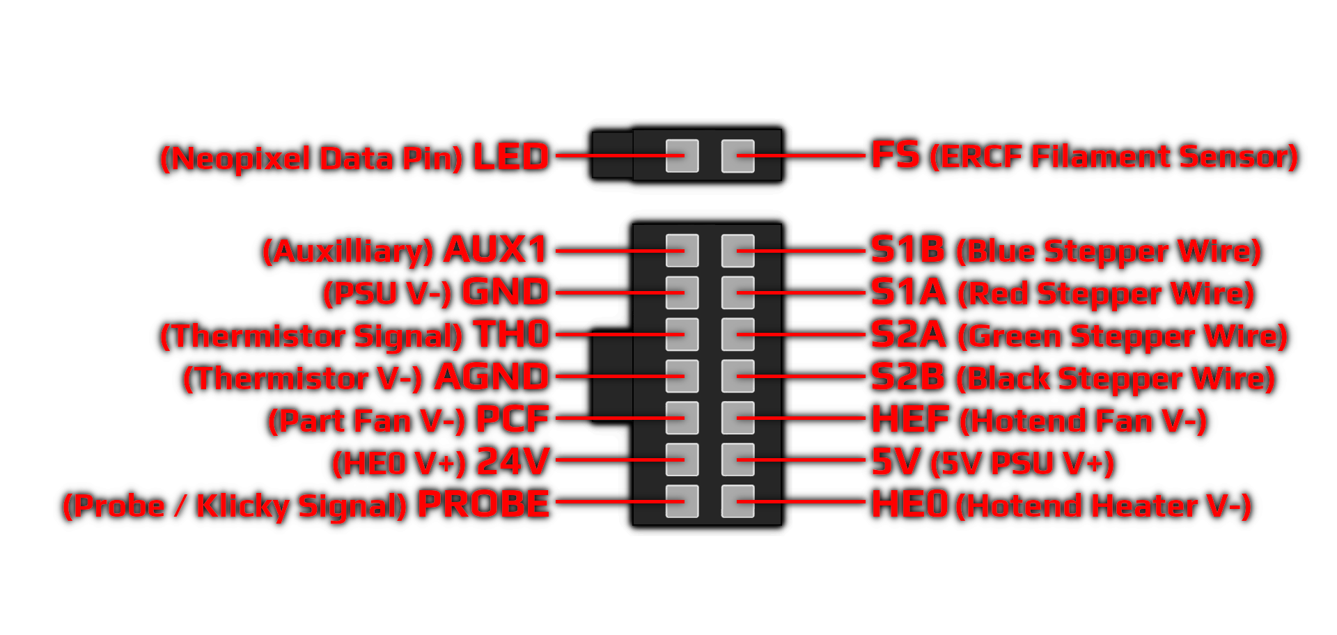
Pinout MCB connector:
Cautions and Advise:
- Be careful when connecting the OptoTap PCB that the correct voltage is selected on the PCB and the Stealthburner PCB
- V3 and V4 of the PCB use a different pinout for the extruder stepper. Please make sure you wire them up correctly
- To make your live easier wiring in the Stealthburner LEDs, you can get them in different variants pre-wired on OneTwo3D
Related Articles
Which version is the Stealthburner or Afterburner Toolhead PCB?
At the moment we are providing version V4.0 (semi assembled only) of the Afterburner PCB , V3.rabbit Afterburner PCB, and the Stealthburner Toolhead PCB as single PCB version (24V) and two PCB version in 5V and 24V.Why has the XY-Microswitch PCB only 4 pins?
The X and Y switches are sharing the same ground potential on the PCB, so the second GND connection from the controller board isn't needed to be wired to the PCB (you can choose if you wire in the X or Y GND). The Vin potential only needs to be wired ...Wiring Diagram of Stealthburner PCB to Octopus controller board
This wiring diagram shows the standard wiring of the HartK Stealthburner PCB to the Octopus controller board:Optotap PCB 5V/24V (2.4.1)
Voltages supported: The OptoTap 2.4.1 PCB supports 5V and 24V supply voltages provided by the probe port of a toolhead PCB or the controller board. Toolhead PCB support: For all revisions of the HartK Stealthburner Toolhead PCB (1pc or 2pcs) you can ...How to use the LDO Toolhead PCB with Clockwork 2?
The LDO Vororn 2.4 kits previous to Rev. C contained the LDO Toolhead PCB which has been designed for the Clockword 1 extruder. From Rev. C the HartK Stealthburner PCB is included, which is compatible with the Clockwork 2 by default. There is a mod ...